
Figure 02 Hardware Architecture: Complete Teardown and Actuator Analysis
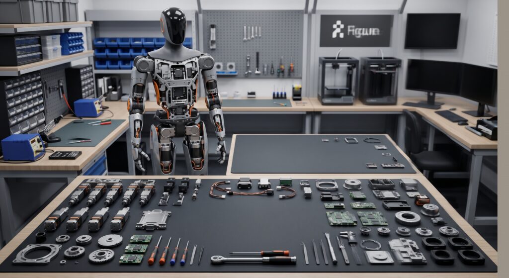
Figure 02 marks the inflection point where humanoid robotics transitions from laboratory-grade proof-of-concept hardware to high-uptime, production-hardened industrial equipment. While the original Figure 01 proved the mechanical feasibility of dynamic bipedal movement in structured settings, it shared common flaws with early experimental platforms: exposed wiring harnesses, off-the-shelf actuators operating near thermal saturation limits, and high vulnerability to factory dust and mechanical pinch points.
Figure 02 discards prototyping shortcuts in favor of bespoke, integrated mechatronic design. Engineered from the ground up for multi-shift automotive manufacturing, the robot encapsulates every high-voltage and communication bus inside exoskeleton-grade castings. Combined with newly designed high-torque density rotary joints, a 16-degree-of-freedom dexterous hand package, and onboard low-latency neural processing modules, the machine sets a fresh design standard for physical artificial intelligence working alongside human operators.
+---------------------------------------------------------------------------------------+
| KEY TAKEAWAYS                                                                         |
| • Exoskeleton Encapsulation: Complete elimination of external harnesses via internal  |
|   slip rings and sealed cast-aluminum rotary passages.                                |
| • 16-DoF Manipulation: Custom hand modules featuring internal palm-mounted motors and  |
|   sub-millimeter optical tactile sensor arrays for closed-loop grip force modulation. |
| • Actuator Engineering: Replaced standard strain-wave drives with cycloidal gearboxes |
|   in high-load lower joints to withstand severe impact and shock loading.            |
| • Dual Embedded Edge Compute: 3x increase in inference throughput, executing VLA      |
|   policies on device without relying on wireless cloud processing pipelines.         |
| • Industrial Pilot Validation: Successful deployment at BMW Plant Spartanburg running |
|   sub-millimeter sheet-metal placement within active production cycle tolerances.     |
+---------------------------------------------------------------------------------------+
Quick Specs: Figure 02 Platform Overview
| Engineering Metric | Specification | System Significance |
| Height | 1.68 m (5 ft 6 in) | 1:1 human workstation and tool clearance parity |
| Total Mass | 70 kg (154 lbs) | Optimized floor loading; decreases kinetic risk in collisions |
| Payload Capacity | 20 kg (44 lbs) | Matches automotive chassis parts and sub-assembly kitting |
| Battery Chemistry / Pack | 2.25 kWh High-Discharge NMC | ~5 hours active duty cycle; supports high burst torques |
| End-Effector Dexterity | 16 DoF per hand | Full anthropomorphic grasp envelope and finger independence |
| Primary Joint Reducers | Custom Cycloidal + Planetary | Extreme shock load tolerance during emergency stops or drops |
| Perception Suite | 6 RGB-D wide-angle cameras | 360-degree spatial point cloud generation; zero blind spots |
| Onboard Compute | Dual System-on-Chip (SoC) | Segregated safety-critical motor control and visual VLA stacks |
Mechanical Architecture: The Shift to Total Internal Harnessing
In harsh factory environments, exposed wire runs and hydraulic lines are the primary drivers of field failures. Friction against stamping tooling, continuous flex fatigue across joint axes, and airborne particulates rapidly degrade exterior conduits. Figure 02 addresses this challenge through complete internal encapsulation.
Every high-voltage DC conductor, Ethernet bus, and controller area network (CAN FD) line runs through sealed hollow-shaft joint assemblies. To maintain continuous mechanical rotation without twisting internal wiring, the engineering team utilized custom slip-ring connectors and continuous flex ribbon channels integrated directly into the structural aluminum castings.
Structural Joint Cross-Section:
[Exoskeleton Aluminum Shell]
  └── [Frameless BLDC Stator]
        └── [Cycloidal Disc Reduction Stage]
              └── [Hollow Bore Passage: High-Voltage Bus & CAN FD Comm Lines]
                    └── [Sealed Bearing & Absolute Position Optical Encoder]
The chassis utilizes a hybrid structural matrix: structural die-cast aluminum alloys form the high-rigidity structural spine and pelvis, while compression-molded carbon-fiber composites shield secondary exterior shells. This balances structural rigidity with minimal parasitic mass. Minimizing overall structural weight directly reduces joint inertia, enabling the control algorithms to execute rapid corrective balancing steps with lower energy consumption per kilometer walked.
Actuation and Kinematics: Why Cycloidal Gearing Replaced Harmonic Drives
Early humanoid platforms relied heavily on strain-wave (harmonic) gearheads due to their zero-backlash characteristics and high single-stage reduction ratios. However, harmonic drives suffer from severe mechanical vulnerabilities under dynamic industrial loads: flexible spline teeth are fragile and prone to catastrophic failure under sudden shock loads, such as tripping or dropping a heavy payload.
Figure 02 transitions primary load-bearing joints—specifically hip pitch/roll and knee flexion—to custom cycloidal reduction drives mated with high-flux-density brushless DC (BLDC) frameless motors.
Kinematic Comparison: Actuation Topologies
┌────────────────────────┬──────────────────────────┬──────────────────────────┐
│ Performance Factor     │ Strain-Wave (Harmonic)   │ Cycloidal Architecture   │
├────────────────────────┼──────────────────────────┼──────────────────────────┤
│ Shock Load Resistance  │ Low (Spline tooth shear) │ Exceptional (Pins/Discs) │
│ Backlash Tolerance     │ Near Zero (0-1 arcmin)   │ Minimal (<1-2 arcmin)    │
│ Torsional Stiffness    │ Moderate                 │ Very High                │
│ Thermal Dissipation    │ Poor via outer cup       │ Efficient housing conduction│
│ Overload Safety Margin │ 200% peak instantaneous  │ Up to 500% momentary     │
└────────────────────────┴──────────────────────────┴──────────────────────────┘
- Cycloidal Mechanics: Because tooth contact is spread across multiple simultaneous load-bearing pins and eccentric rolling discs, cycloidal gears withstand up to 500% momentary shock loads without stripping teeth.
- Thermal Dissipation: High continuous torque generation produces significant thermal buildup in motor coils. Figure 02 routes motor stators directly against aluminum housing members, turning the structural limbs into passive heat sinks. This design prevents thermal throttling during extended lifting sequences.
- Dual Absolute Encoders: Every active joint incorporates high-resolution magnetic and optical encoders on both the input motor shaft and output limb axis. This gives the low-level motor controllers sub-millimeter position tracking, eliminating joint position drift over multi-hour runtimes.
16-DoF Dexterous Manipulation and Tactile Sensing Skin
Industrial part manipulation requires more than parallel-jaw grippers. Automotive assembly plants rely on flexible human fingers to grasp sheet-metal brackets, insert rubber grommets, and pick loose parts from deep bins. Figure 02 integrates fully articulated hands that mirror human kinematic scale and freedom of movement.
Figure 02 Manipulator Architecture:
[Forearm Sub-Assembly: High-Bandwidth Motor Drivers]
       │ (CAN FD High-Speed Bus)
[Palm Core: 4 Micro-Brushless Miniature Actuators]
       ├──> Thumb Module: Dual-Axis Rotational Opposition
       └──> Finger Tendon Routing: High-Tensile Synthetic Polyethylene Filaments
              │
       [Tactile Sensor Matrix: Dynamic Surface Force Measurement]
- Kinematic Actuation: Each hand provides 16 mechanical degrees of freedom. Actuation power is housed within the wrist and palm packages, avoiding the bulk of forearm cable conduits. Micro-brushless motors drive high-tensile synthetic tendons connected to multi-link digit joints.
- Tactile Optical Sensor Array: Traditional strain gauges only measure bulk resistance. Figure 02 lines the finger pads and palm surfaces with high-density tactile sensor arrays. These sensors capture micro-deflections in flexible skin layers, granting the control system immediate feedback on surface friction and slip tendencies.
- Closed-Loop Force Control: When handling fragile components, such as painted exterior panels or electronic boards, the robot does not rely on visual confirmation alone. Local tactile loops run at hundreds of Hertz, modulating grip pressure dynamically within milliseconds of detecting shear slip.
Real-World Validation: The BMW Plant Spartanburg Pilot
While computer simulations validate general control concepts, physical manufacturing tests reveal the actual viability of bipedal robotics. Figure 02 underwent sustained operational trials at the BMW Group assembly plant in Spartanburg, South Carolina, focusing on precision sheet-metal placement within fixture jigs.
The video breakdown below captures Figure 02 operating on the production floor at BMW Group Plant Spartanburg, demonstrating sheet-metal insertion and cycle-time endurance:
Factory Deployment Video Reference:
Watch the platform in production:BMW Group advances Physical AI with Figure in production
(Watch for: sub-millimeter peg-in-hole alignment, self-stabilizing bipedal stance under uneven load, and fluid dual-arm coordination).
During this deployment, the robot was tasked with locating stamping sheet metal from transport dollies and inserting the panels into precise manufacturing fixtures. This process demanded:
- Millimeter-Level Alignment: Locating locating pins into sheet metal slots without bending the metal or binding the jig.
- Dynamic Center-of-Gravity Shifts: Maintaining steady footing on concrete floors while swinging a heavy steel stamping away from its core centerline.
- Production Line Safety Integration: Operating in work zones adjacent to logistics tuggers and automated guided vehicles (AGVs) while honoring strict speed and separation safety zones.
Neural Processing Architecture and the Embodied VLA Pipeline
Operating reliably in dynamic industrial environments requires significant onboard computing. Offloading low-level balance or perception loops to Wi-Fi networks introduces dangerous latency spikes and signal dropouts that can cause a walking biped to fall.
Figure 02 operates an entirely self-contained compute setup using a dual System-on-Chip (SoC) configuration running a real-time, low-latency Linux kernel.
Hardware Control & AI Execution Pipeline:
┌──────────────────────────────────────────────────────────────┐
│ HIGH-LEVEL VISUAL & COGNITIVE STACK (20 Hz - 50 Hz)          │
│ • 6x RGB-D Camera Inputs                                      │
│ • Vision-Language-Action (VLA) Model Execution               │
│ • Scene Semantic Segmentation & Dynamic Grasp Planning       │
└──────────────────────────────┬───────────────────────────────┘
                               │ High-Speed Internal Bus
┌──────────────────────────────▼───────────────────────────────┐
│ LOW-LEVEL MOTOR KINEMATICS STACK (1000 Hz)                   │
│ • Whole-Body Model Predictive Control (MPC)                  │
│ • Zero-Moment Point (ZMP) Dynamic Balancing                  │
│ • Joint Torque Control & Closed-Loop Actuator Safety Clamps   │
└──────────────────────────────────────────────────────────────┘
- The Vision-Language-Action (VLA) Model: Rather than programming custom trajectory arcs for every individual automotive component, Figure 02 runs an integrated vision-language-action policy. The model translates visual camera tokens directly into continuous end-effector movement vectors, allowing the robot to adjust its grip dynamically if a sheet-metal part sits skewed on the rack.
- Sim-to-Real Acceleration: Thousands of manipulation permutations are trained inside physics simulation environments using NVIDIA Omniverse and Isaac Lab. Synthetic variations in lighting, surface reflectivity, and part positioning train the neural networks before the model weights ever touch physical robot hardware.
- Fail-Safe Hardware Interrupts: If high-level neural networks stall or miss an inference deadline, lower-level control loops maintain balancing posture. If safety sensors detect an unavoidable collision, the joint actuators engage dynamic regenerative braking and mechanical damper locks to prevent an uncontrolled structural fall.
Commercial Outlook: Unit Economics, RaaS Models, and Factory ROI
The commercial success of humanoids like Figure 02 depends on straightforward manufacturing economics. Factory executives assess humanoids through the lens of overall Total Cost of Ownership (TCO) compared to dedicated automation and human labor overhead.
Hourly Operating Cost Breakdown ($/Hour):
Human Operator (US Automotive):  $45.00  [████████████████████████████████████]
Dedicated Fixed Gantry Machine:  $28.00  [██████████████████████]
Figure 02 Robot-as-a-Service:    $16.50  [█████████████]
- Human Assembly Costs: In North American automotive plants, fully burdened human labor costs—incorporating wages, overtime, healthcare, and workers’ compensation reserves—consistently range between $38 and $52 per hour.
- The RaaS (Robot-as-a-Service) Advantage: Under multi-year RaaS deployment contracts, Figure AI targets lease pricing of $14 to $20 per operational hour. This structure eliminates millions of dollars in upfront capital expenditure for the factory, shifting automation spending into predictable operational costs.
- Flexibility vs. Hard Automation: Traditional robotic cells require expensive concrete anchoring, safety fencing, custom PLC panels, and dedicated conveyor systems that take months to re-tool when a vehicle model changes. A mobile biped walks directly up to standard manual workstations, uses the same human-scaled fixtures, and re-programs via software updates rather than structural mechanical modifications.
Figure 02 proves that modern general-purpose humanoids are moving beyond lab demos toward dependable industrial workhorses. Over the next several production cycles, the deciding performance benchmark for Figure and its competitors will shift away from kinematic stunts toward Mean Time Between Failures (MTBF) exceeding thousands of continuous run-hours on active factory floors.
Explore related models and hardware specifications in our Bot.to Humanoid Directory or compare direct engineering benchmarks in our Figure 02 vs. Tesla Optimus Gen 2 Head-to-Head Breakdown.
